This article will advise on high pressure liquid chromatography pump design considerations that can help engineers meet industry pressure demands of 20 000psi and above.
Challenges of Designing a High Pressure Pump
For the past three decades designers of critical liquid chromatography (LC) pumps have been witnessing a steady increase in demand for machines that can handle higher pressures.
Driving this demand are end users who say they need higher pressure to achieve better sample resolution and higher throughput rates, and manufacturers (keen to satisfy users’ needs) who are asking engineers to build in more pressure capacity with the goal of launching the most competitive, cutting-edge technology.
By working with their seal suppliers, engineers have been able to meet this growing demand, and the increasing pressures have served to propel instrument technology and performance improvements of nearly 1900% since the mid-1970s. As a result, countless life-improving drugs and diagnostic processes have been developed.
But over the past two or three years a new problem has emerged. The race for higher pressures has outpaced the industry’s ability to solve the complex challenges of generating and maintaining them.
Today, high pressure pump engineers face the formidable task of achieving reliable, consistent operation at 20 000 psi and above. And because of limitations in material capabilities and current pump designs, they can no longer rely solely on a seal to get them there.
To shatter the 20 000-psi barrier, engineers will first have to break from the “rut” of traditional design approaches and sealing technology, and adopt a more holistic perspective that may include hardware design changes. If they do not, they may find it increasingly difficult to tell the difference between a rut and the “grave” prospect of significant market-share loss.
High Pressure Pump Design Considerations
While the increasing pressures of LC have never been a simple challenge, the new requirements have stretched existing technology to its limits. It is becoming clear that the industry can no longer expect to reach its pressure goals by focusing only on seal designs or materials.
Engineers should consider changes that will enable the pairing of pump and seal to break the 20-kpsi barrier.
Some major factors to consider when designing an LC pump include:
- Shaft diameter, material, and surface finish
- Drive mechanism/ linkage
- Heat dissipation
- Plunger guidance
- Media viscosity
- Stroke length
- Peripheral components
- Seal installation
- Failure criteria
- Test criteria
Below, we’ll discuss these design considerations in further detail.
Shaft Diameter, Material, and Surface Finish
When sealing for ultra-high pressures, the primary requirement is meeting accurate flow rates. This goal is what drives the plunger diameter, stroke length and speed. This is an area where sealing and pump operating requirements will compete. There is a very fine line for best sealing and plunger reactions when building cylinder pressure.
One major cause of early seal leakage is mechanical plunger side-loading. This happens when the plunger movement transfers its load against the seal’s inside sealing surface. To avoid this, we recommend a design that enables the plunger ferrule, linked to the drive system, to provide optimal alignment. In time, side-loading will prematurely wear the seal material and increase the inside sealing diameter. Shortening the stroke will not always reduce side loading if the plunger is not aligned in the linkage properly.
Plunger size also plays an important role in seal life, performance, and response to rapid pressure changes.
Smaller plungers experience lower loads at ultra-high pressures, but the seal also must be small, and must be capable of withstanding the pressure. This leads to limited flexibility, especially during aspiration (vacuum) and/or transition to the pressure stroke.
Maintaining some flexibility is important in order to ensure proper sealing contact stress along the entire stroke.
For a plunger material we recommend sapphire, a mono-crystalline material. It is the optimal choice for contact with thermoplastic seal material, because it allows for a better surface finish and hardness.
This is critical when you are trying to meet leakage rates in micro-liters or nano-liters. The adhesion factors of a soft thermoplastic and very hard sapphire material will minimize this condition.
Zirconium ceramic (TZP) has emerged as the material of choice for some low to moderate pressure LC pumps. Although its hardness is similar to that of sapphire, its variability can present challenges when applied in HPLC. It is available in many different types, and each type varies in grade, grain, physical structure and size, which can affect stability.
Recommendations:
- Specify extremely smooth surface finishes (less than 1 Ra).
- Specify hardness greater than 70 Rc.
- Choose pure sapphire plungers.
- Design a plunger with a diameter of less than 2.1 mm (0.082 inch).
Drive Mechanism/Linkage
When designing the drive mechanism, it is crucial to consider how the plunger will be attached and to compensate for pulsation during the pumping operation.
The speed and stroke length will vary plunger-side loading, which can cause premature wear on the seal.
Synchronization of the pump linkage is also critical, as the winner in the battle between variable speed and pulsation will be determined by the drive mechanism. Synchronization becomes a concern only if the plunger’s return spring is insufficient because of seal friction.
Recommendations:
- Design a sufficient drive system to compensate for seal friction.
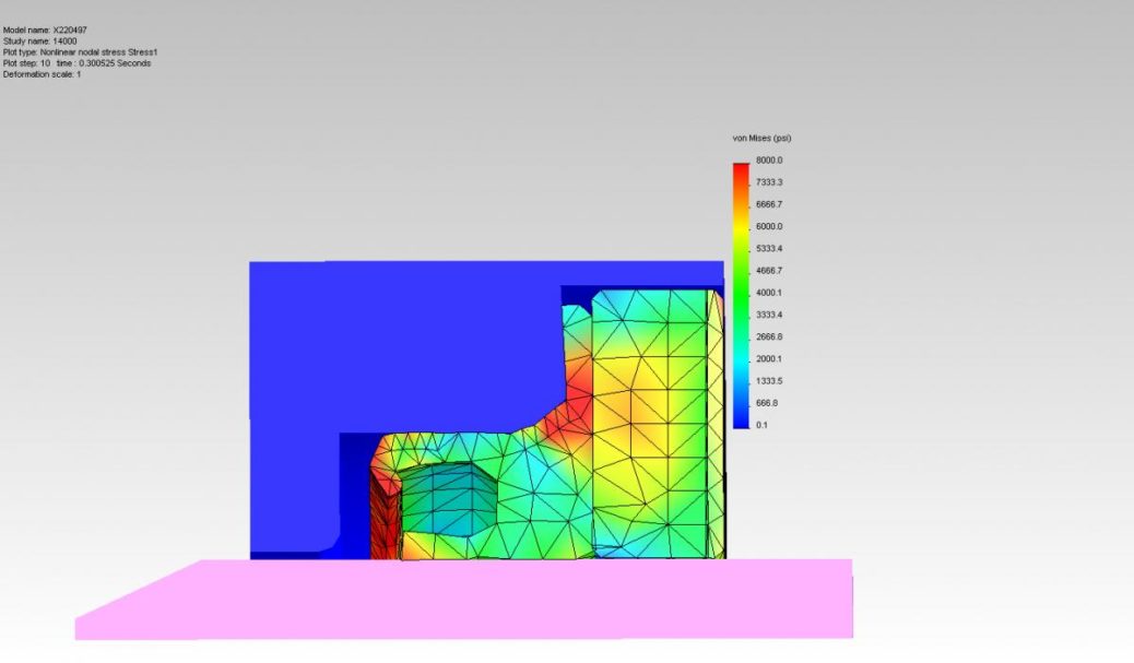
- Ensure precise attachment between the plunger ferrule to plunger mount – allow to float (for centering purposes) as well as firmly withstand any vertical and or horizontal movements (also see box ‘The perfect piston?’).
- Include a strong plunger return mechanism to compensate for seal friction during the aspiration stroke.
Heat Dissipation
Friction heat created under pressure can dramatically affect sealing performance. Therefore, we recommend that pump designers keep dissipation in mind.
Pressure created in the forward stroke, or by the seal and its energizer, can cause sealing contact stress to the plunger surface. Extreme effects occur in the forward stroke under ultra-high pressure, and in that moment the sealing contact stress is so great that seal material shear stress is overtaken, causing wear or shedding.
As a result, material can sometimes be seen in the frit (inline fluid debris filter), the tubing or even around the seal energizer.
Recommendations:
- Use an active wash system.
- Maintain a service pressure/velocity (PV) within seal material limits.
- Specify an ultra-smooth plunger surface finish (less than 1 Ra).
Plunger Guidance
A major mechanical disadvantage to high-pressure sealing is plunger side-loading. This off-axis travel of the plunger under the forward stroke physically changes the seal’s inside form, and can lead to catastrophic failure.
Historically, LC pumps were designed with a large plunger-size to long stroke-length ratio (for instance, 3:1).
With the advent of ultra-high pressure pumps these plungers caused early seal and back-up support failure. A solid linkage type and/or plunger size to stroke, which is closer to 1:1, should be used in order for the seal back-up to absorb some of the remaining micro-side load.
We recommend using a solid linkage. It is important to keep it concentric to the wash body and pump head.
Recommendations:
- Ensure tight concentric guidance exists between the wash body and pump head (less than 0.05 mm).
- Use a high modulus back-up support ring.
- Use a high modulus guide ring.
Media Viscosity
Currently, most pumps are designed to handle all media types — from low viscosity co-solvents, such as methanol, to high viscosity media, such as disodium phosphate buffers, and everything else in between. Pumps are not typically designed to perform optimally under any given media, as during testing and approval most only experience co-solvents.
Seals perform better in low viscosity media, so engineers may expect different results when using higher viscosities. Degassing apertures can also play a key role in the efficiency of very small diameter plunger seals.
Any trapped air starting within the seal-bore area and travelling downstream towards the flow restrictor will affect pump pressure readings.
Recommendations:
- Manage sealing contact stress by using low viscosity media.
- Expect variable contact stress when using high-viscosity media.
Stroke Length
Stroke length should be minimized and well-guided to ensure the plunger is concentric to the wash body and pump head bore throughout the pressure and aspiration stroke.
This is especially important during the pressure stroke when the plunger is most prone to side-load the seal back-up and wash body seal.
When shortening the stroke length to meet a desired flow rate, the plunger speed must increase. This, in turn, increases the system PV.
To maintain long seal life, we recommend keeping system PV within the limits of the seal material PV.
Recommendations:
- Use a design with a 1:1 ratio plunger diameter to stroke length.
- Ensure a strong supporting linkage exists between the plunger ferrule and drive.
- Align the system PV with the seal material PV limit.
Peripheral Components
It is important to consider the effects of peripheral hardware. For example, check valves, columns, fittings and tubing during system testing for sealing performance, as these elements can cause false positives during testing.
Check valves not rated for proper pressure, weak tubing connections, underrated columns and/or pressure restrictors are just a few potential causes.
Verifying fittings and tubing requirements carefully, as start-up leaks typically originate in peripheral components.
Recommendations:
- Ask your vendor to pre-cut tubes – do not cut them yourself.
- Use proper tools to attach fittings, with proper torque values, or delegate this task to service professionals.
- Use a proper rated column and flow restrictor to test pressure characteristics.
Seal Installation
By setting and following an established seal installation process engineers can avoid seal damage and ensure proper seal alignment inside the pump head.
This is critical because start-up failures and leaks can result from improper installation/seating of the seal in the housing.
Recommendations:
- Use approved installation tools.
- Verify seal position and integrity.
Failure Criteria
Understanding how much leakage is occurring and where potential leaks could originate is most crucial to establishing failure criteria for pump heads, check valves, fittings, pressure transducers, the wash body, sensors and tubing, among other areas/
It is difficult to discern cause when you are working with firmware, multiple conditions (exceeding 10) and hardware combinations.
Often, what was initially identified as a seal failure turns out to be a false positive or negative.
Recommendations:
- Establish multiple failure conditions for each media type — as well as for each flow rate or speed.
- Establish leakage by sensors, volumetric changes and pressure drop programmatically, and minimize manual data collection.
Test Criteria
There are many ways to establish and correlate test criteria that simulate field conditions.
An accelerated test to determine overall pump performance will not necessarily represent actual field use, but it may induce plunger behavior that will shorten seal life through side-loading or increased frictional heat.
Also, establishing back pressure to simulate normal pump runs through a column will skew performance requirements.
Recommendations:
- Use capillary tubing for back pressure.
- Avoid needle valves – they typically fail or create false negative and positive above 10 kpsi.
- Test with a column, if it is possible, though it may be hard to find anything rated above 17.5 kpsi.
High Pressure Pump Design Consultation
The sealing professionals at Bal Seal Engineering can participate in the pump development process as your innovation partners. If you’d like to consult with one of our engineers about elevating your pump design to operate at higher pressures, click here to submit a design request form.