Performance requirements for in vitro diagnostics (IVD) equipment—including clinical, hematology, and urine analyzers—are outpacing capabilities. Increasingly, the IVD industry is seeking equipment that lasts at least three years or more compared with the existing standard one-year maintenance program. This demand for extended service life and less-frequent maintenance cycles is forcing design engineers to take a closer look at every facet of analyzer design, with a focus on extending the lifetime of the pump.
This article explores three solutions designed to help prevent premature pump failure and propel IVD equipment toward the industry goal of three-year periodic maintenance. Beginning with an examination of the most common causes of IVD seal failure, it illustrates the relationship between hardware tolerances, proper piston alignment, and seal service life. In particular, it addresses the benefits of using active wash systems with rinse seals and how custom seal designs can dramatically improve IVD pump precision and longevity.
Trends driving change
The three primary types of diagnostic analyzers include hematology analyzers (HbA1C testing and blood cell count), clinical analyzers (protein analysis, genome development, chemical analysis), and urine analyzers (fluorescence flow cytometry, and digital imaging). The tasks these analyzers perform differ widely, but in all cases, the goal is the same—laboratory end users want the systems to run for longer periods with reduced maintenance requirements. This puts the burden on design engineers to enhance the equipment, improve the hardware, and increase the life span of their devices, while also minimizing manufacturing costs. OEMs, therefore, are investigating new designs in order to expand the life span to a minimum of three and in some cases up to 10 years to ensure that equipment lasts longer in the field.
Application conditions
Clinical analyzer equipment is comprised of various mechanisms working together to perform an analysis. In each system, there is a pump that pressurizes the media (typically a reagent) and then dispenses the reagent. The pump runs at a low speed in a reciprocating motion with a stainless steel or ceramic plunger of 2–12.7 mm (0.078–0.5 in.) in diameter. The housing is made from aluminum, stainless steel, or a machined or molded plastic. The temperature of the application runs from ambient to 104 °F (40 °C). Smaller systems may contain one pump, while larger systems may contain multiple pumps that perform more than 200 assays an hour (see below, “Application conditions”).
Preventing common causes of seal failure
These analyzers are generally expected to operate for more than 1 million cycles, and the environment in which the low-speed reciprocating pumps operate can become harsh. The media is typically a reagent, which can weep slightly past the seal inner diameter (ID) lip and pool behind the seal. Once the reagent dries out, it can become very aggressive as it crystallizes on the plunger and under the seal lip. When that salt rubs under the seal ID lip, it can scratch the dynamic sealing surface, and over time the scratches become leak paths for the media to flow. This, in turn, produces inconsistent volume delivery for the pump, resulting in inaccurate results. The salt crystallization damages the seal, increases seal wear, and reduces seal life.

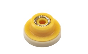
Central to the performance of the IVD pump is the seal that protects it (see Figure 1). A leaking seal can lead to catastrophic failure, inaccurate volume delivery, and system breakdown. It is exposed to high cycles and harsh media, yet it must adhere to strict, minimal leakage criteria of less than 500 nL/min for prolonged periods. Adequate hardware tolerances, proper piston alignment, and the right seal work together to prevent pump breakdown. Examples of effective seal designs are shown in Figures 2–5.
 Figure 2 – Spring-energized seals prevent the ingress of aggressive media into pump electronics.
 Figure 3 – Seals control weepage and help prevent the saline-rich reagent from forming salt crystals in the equipment.
Hardware recommendations. The pump consists of multiple pieces—the pump head, the rinse portion, and the back plate, which together can result in a greater tolerance than anticipated in the design. Each hardware piece has an allowable amount of tolerance for manufacturing practices. When all hardware components are assembled, the tolerance stack-up may cause the pump to be nonconcentric resulting in shaft-to-bore misalignment (STBM). Excessive STBM may result in extreme wear on one side of the seal and cause the plunger to contact the housing, scratching or damaging the plunger in the process. To reduce STBM, a floating plunger assembly is recommended because it reduces side-loading and ensures consistent pump performance. A fixed plunger alignment is not recommended. When a pump is not performing to expected number of life cycles due to premature leakage, STBM is often the cause.
Selecting the right plunger material, surface finish, hardness, and tolerance also affect pump performance. A plunger with a high hardness (above 50 Rc) and a smooth surface finish of 7.3–14.5 µin. Ra will improve seal life and pump performance. Smoother surfaces prevent seal wear and extend pump performance. Plunger materials such as a ceramic or sapphire plunger have excellent surface finish and high hardness with minimal porosity. Alternative plunger options include stainless steel with a hardness treatment and/or polished to meet the surface requirements.
Housing material, hardness, and surface treatment are key to consistent performance. A housing material that has a high hardness above 30 Rc and a smooth sealing surface of 9.1–14.5 µin. Ra enhances pump life by reducing seal wear. A machined metal housing is preferred because it ensures tight manufacturing tolerances and thus prevents lot-to-lot variation.
To reduce costs, some manufacturers may propose a larger tolerance for the seal groove geometry—the machined channel in which the seal sits. This is not recommended. If the seal groove is larger than the seal, then the seal may shuttle or move within the groove, which introduces micro-air bubbles into the system and/or causes system pulsation. Once this occurs, the seal experiences excessive wear and the pump then dispenses inaccurate volumes. Other hardware concerns include the method of hardware installation, such as the screw installation pattern, which can negatively affect piston alignment. Developing an appropriate sequence to tighten the screws (such as a star-pattern) is paramount to consistent installation practices.
From a machining perspective, it is important to maintain a very tight tolerance of <±0.001 in. for the groove in larger diameters of >0.500 in. and much tighter hardware tolerances for smaller diameters below 0.250 in. Radial clearance between the housing and the plunger should be 0.002 in. max.
Active wash systems and rinse seals. Having a rinse system behind the seal has become industry standard in the past few years, which has greatly improved pump performance, especially when fighting against a media that is so aggressive in its solid state. The rinse portion is essential for removing media buildup and dramatically improving equipment life.
With no rinse portion in the system, the reagent media will dry out and crystallize behind the high-pressure seal, and as the dynamic seal lip reciprocates over the crystals, the crystals can scratch the seal inner diameter (ID). Over time, these scratches become leak paths. An active wash system with a rinse seal prevents this crystallization. Rinsing behind the seal breaks down salt crystals so that the crystallization does not occur, which, in turn, minimizes the potential damage to the seal. This prevents particle generation shedding, thus reducing process contamination. It also reduces the heat generated under pressure and adds lubricity to the application.
The backup ring. Ahigh modulus backup support ring behind the seal can prevent some plunger misalignment because it allows for more concentric movement of the plunger. It improves alignment by taking the brunt of the plunger misalignment and reduces any potential side-loading on the dynamic seal ID lip. Typically, the backup ring is made from a virgin PEEK material, known as P41 HT. This clean material is FDA compliant. Virgin PEEK material has higher extrusion resistance preventing the seal from extruding beyond the backup ring, which could reduce the amount of contact stress between the seal ID and plunger. The superior tensile strength of the backup ring withstands any plunger misalignment. A softer material would deform under the high force of the plunger, but the virgin PEEK backup higher tensile strength of 14,000-psi min. pushes the plunger into proper alignment and prevents seal deformation. Tight tolerances on the backup ring are essential for two reasons: 1) for proper alignment on the plunger itself, and 2) to ensure that a pool of saline media is not building up. While all seals are designed to prevent media ingress, a slight amount of weepage does occur that can build up over time. Having a backup ring to help prevent media pooling is vital to ensuring a longer life.
 Figure 4 – When choosing a seal for reciprocating applications, you must consider temperatures, pressure, speed, and media.
To increase pump life, the seal needs to address potential leakage in both the ID and outer diameter (OD) of the seal. Some seal designers, such as Bal Seal Engineering, Inc. (Foothill Ranch, CA) are creating nonstandard seals that address these causes of pump failure. The geometry of these custom-engineered seals, combined with proper jacket material and energizer, ensure that there is no media pooling in empty or dead-volume areas.
Geometries. A non-flange seal with a long ID lip can increase contact area for tighter tolerances and is easier to machine. However, a flange design simplifies installation and provides a secondary OD seal, and its short ID lip reduces friction. Because the OD of the seal is a static surface, creating an added amount of compression on the seal geometry helps prevents OD seal leakage. For example, when the plunger is retracting, the aspiration stroke creates an almost a vacuum-like condition. When that happens, the seal lips want to move inward toward the spring energizer, but the seal lip geometry is designed to ensure that it doesn’t start to cave in, thus preventing OD leakage from occurring.

Materials. For these applications, which generally require low-speed reciprocation and low friction, the recommended seal jacket material is a virgin ultrahigh molecular weight polyethylene (UHMWPE) such as Bal Seal Engineering’s UPC-16. It has excellent wear resistance in water and other aqueous applications, and is suitable for low-speed, low-pressure service. It is recommended for applications at temperatures from –450° to +180 °F (–268° to +82 °C). This dense material produces minimal seal wear particles. It prevents media permeation, though it may generate higher friction on the plunger.
Virgin or polyimide-filled polytetrafluoroethylene (PTFE), which has a low coefficient of friction, can also be used for the seal jacket material. However, UHMWPE is preferred for an aqueous media and is better suited for the forces associated with these applications. UHMWPE is a pure material, which means that no contaminant or foreign particulate is left inside the system.
In some cases, a more robust material may be needed. A filled polyethylene, such as Bal Seal Engineering’s UP-30, offers even more lubrication, which some manufacturers may need if the system will be running dry for a period of time. UP-30 is also a UHMWPE material that has been optimized for use in pumps where long life is expected and is an FDA compatible material where the majority (97% or more) of the ingredients have received an FDA “safe for use in food contact” review.
Energizer. While the seal jacket geometry prevents leakage at high pressures above 1,000 psi, the spring energizer is designed to help the seal prevent leakage at low pressure. Because the pressure is fairly low at 3,000 psi and below, a medium force spring applies consistent sealing pressure over large tolerance range. It is important to ensure that there is adequate contact stress on the seal lip but not so much friction or force on the plunger that it causes the pump to stutter. An energizer made of 316 stainless steel or Hastelloy is bio-inert and prevents corrosion and oxidation.
Backup ring. The backup ring, which is often included to ensure alignment and to prevent pooling behind the seal, can also provide additional life. Whether manufactured in house or by the seal provider, it is essential that the backup ring dimensions match the other seal components to ensure that the seal meets the tight tolerances required. If the backup ring is not concentric or is too large, it can adversely affect seal performance by contacting the plunger and generating particles or increasing the friction in the application. Ceramic plungers have high surface finish requirements, and a stainless-steel backup ring can easily scratch the plunger and cause damage beyond repair, which is why a polyetheretherketone (PEEK) material is recommended for a backup ring. In some cases, when pressures exceed 5,000 psi, a backup ring can prevent material from extruding into any empty space. The less the seal material moves, the longer life the equipment will have.
Conclusion
Preventing premature pump failure is essential as the IVD industry moves toward a longer maintenance cycle for its analyzers. Addressing the common causes of IVD seal failure, including hardware tolerances, proper piston alignment, and seal service life, are all part of the solution. But to eliminate costly mistakes and delays, manufacturers must consider sealing requirements as part of overall pump design in the early design stages. The seal geometry, along with its jacket material and energizer, are integral to the efficiency of the pump and thus the overall life span of the analyzer equipment.
This article first appeared in Labcompare.
